
Quick answer: To scale a Modbus tag in a Modbus OPC server, open the tag in Integration Objects’ OPC Server for Modbus, check Enable Scaling, enter the raw input range (for example 0 to 4095) and the engineering range (for example 0 to 100 bar), choose Linear or Square Root and a Scaled Type such as VT_R4 (Float), then save and restart the service. OPC clients then read values in engineering units, with no conversion logic of their own.
Modbus devices rarely deliver data in engineering units. A pressure transmitter wired to a PLC (programmable logic controller) analog input usually shows up as a raw count, for example 0 to 4095 for a 12-bit converter, and an HMI (human-machine interface), historian, or SCADA (supervisory control and data acquisition) client then has to convert that count into bar, °C, or m³/h. Integration Objects’ OPC Server for Modbus, a Modbus OPC server that exposes Modbus TCP and serial devices to OPC DA (Data Access) clients, can now do that conversion itself with the new Tag Scaling feature, so every OPC client receives values that are ready to use.
This tutorial explains how scaling works in the OPC Server for Modbus, and how to configure it from the graphical user interface, both on new tags and on tags that already exist.
Key takeaways:
-
Tag scaling converts raw Modbus register values into engineering units inside the Modbus OPC server, before the data reaches any OPC client
-
Two scaling types are available: Linear for most analog signals, and Square Root for differential-pressure flow transmitters
-
Each tag has its own raw range, scaled range, Scaled Type, units, clamping and negation settings
-
Writes from OPC clients are converted back to raw values automatically
What Is Tag Scaling and Why Use It?
Tag scaling is the conversion of a raw Modbus register value into a value in engineering units, performed by the Modbus OPC server itself. Scaling maps a raw input range, which is the value read from the Modbus register, onto a scaled range in engineering units. The OPC Server for Modbus applies the conversion on every read before it publishes the value, and applies the reverse conversion on every write before it sends the value to the device. This brings several benefits:
- One place to maintain conversions: the conversion is defined once in the OPC server instead of in every HMI, historian, and report.
- Correct data types for clients: a 16-bit integer register can be exposed as a Float (VT_R4) or Double (VT_R8), so clients receive decimal values.
- Engineering units: the unit text, for example “bar” or “m3/h”, is published with the tag.
- Safe ranges: optional clamping keeps out-of-range readings inside the configured scaled limits.
- Flow measurement support: square-root scaling linearizes signals from differential-pressure flow transmitters.
How Scaling Works in the OPC Server for Modbus
Each tag has its own scaling settings. When scaling is enabled, the value read from the device goes through the scaling stage and is published to OPC clients with the selected Scaled Type as its canonical data type:
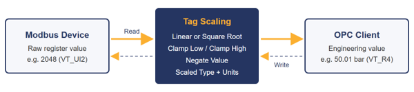
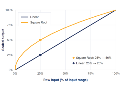
Two scaling types are available:
- Linear: the scaled value is proportional to the raw value. This suits most analog signals, such as 4–20 mA transmitters and counts from A/D (analog-to-digital)
Scaled = (Raw − Min Input) / (Max Input − Min Input) × (Max Scaled − Min Scaled) + Min Scaled
- Square Root: the scaled value is proportional to the square root of the normalized raw value. This suits differential-pressure (DP) flow transmitters, where flow varies with the square root of the measured pressure difference.
Scaled = √[(Raw − Min Input) / (Max Input − Min Input)] × (Max Scaled − Min Scaled) + Min Scaled
How to Configure Scaling on a Modbus Tag
Scaling can be configured when you add a new tag, or added later to a tag that already exists. This section assumes that a Modbus device is already configured. If not, follow our guide How to Configure OPC Server for Modbus to Collect Data from Modbus Devices first.
Download OPC Server for Modbus
Add a New Modbus Tag with Scaling
- From the start menu or your desktop, right click on the “OPC Server for Modbus” shortcut and select “Run as administrator” to open the configuration interface.
- In the “Address Space” tree, right click on the device (or on one of its groups) and select “New Tag” from the displayed menu.
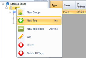
- In the “New Tag” dialog, configure the tag parameters:
- Name: A unique name for the tag.
- Location Type: The Modbus data area: Coils, Discretes Input, Input Registers, or Holding Registers.
- Address: The address of the register in the device.
- Data Type: The raw type stored in the Modbus register, for example VT_UI2 (Unsigned Short) for a 16-bit analog input.
- Units: Optional engineering unit, for example “bar”. The unit is published to OPC clients with the tag.
Scaling applies to numeric register values. For bit tags, such as Coils, the “Item Scaling” section stays disabled.
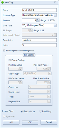
- In the “Item Scaling” section, check “Enable Scaling” and configure the scaling parameters:
- Min Input Value / Max Input Value: The raw value range read from the device, for example 0 to 4095 for a 12-bit A/D converter. Both limits must fit in the raw Data Type.
- Scaled Type: The data type of the value published to OPC clients: VT_I2 (Short), VT_UI2 (Unsigned Short), VT_I4 (Integer), VT_UI4 (Unsigned Integer), VT_R4 (Float), or VT_R8 (Double). Select VT_R4 or VT_R8 to keep decimal values.
- Min Scaled Value / Max Scaled Value: The engineering range that corresponds to the input range, for example 0 to 100 bar. Both limits must fit in the Scaled Type.
- Clamp Low: When set to “Yes”, scaled values below Min Scaled Value are replaced by Min Scaled Value.
- Clamp High: When set to “Yes”, scaled values above Max Scaled Value are replaced by Max Scaled Value.
- Type: The scaling type, either “Linear” or “Square Root”.
- Negate Value: When set to “Yes”, the sign of the scaled value is inverted before it is published.
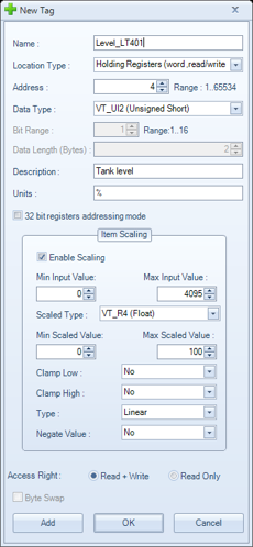
- Click “OK” to create the tag and close the dialog, or click “Add” to create the tag and keep the dialog open for the next one. The name and address are then incremented automatically. The interface checks the scaling parameters and displays an explicit message if a value is invalid, for example when Min Input Value is greater than Max Input Value, or when a limit is outside the range of the selected data type.
Enable Scaling on an Existing Tag
- In the “Address Space” tree, expand the device and right click on the tag, then select “Edit” (or press F1).
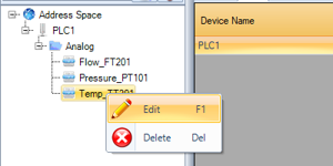
- The “Edit Tag” dialog shows the current tag configuration. While “Enable Scaling” is unchecked, the tag returns the raw value read from the device.
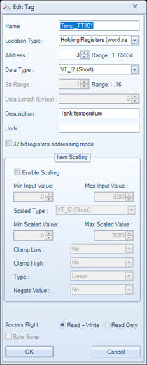
- Check “Enable Scaling”, configure the scaling parameters as described in step 4 of the previous section, then click “OK”. To return to raw values later, edit the tag again and uncheck “Enable Scaling”.
Apply and Verify the Configuration
- Click the “Save” button to save the configuration (.csv) file.
- Restart the OPC Server for Modbus service from the “OPC Server” menu for the configuration changes to take effect.
- Connect to the OPC Server for Modbus using an OPC DA Client and read the tag. The value is now published in engineering units, with the Scaled Type as its data type. You may use our free OPC DA Test Client product available for download from our website.
Modbus Scaling Examples: Raw vs. Scaled Values
The table below shows the values returned to an OPC client for typical configurations:
| Configuration | Raw value | Value read by the OPC client |
| Linear, 0…4095 → 0…100, VT_UI2 → VT_R4 | 2048 | 50.01221 |
| Linear, 100…500 → −50…50 | 100 / 300 / 500 | −50 / 0 / 50 |
| Linear, 0…65535 → 0…65.535, Units “m3/h” | 40000 | 40 m3/h |
| Square Root, 0…10000 → 0…100 | 2500 | 50 |
| Linear, 100…500 → −50…50, no clamping | 50 / 600 | −62.5 / 75 |
| Linear, 100…500 → −50…50, Clamp Low and Clamp High = Yes | 50 / 600 | −50 / 50 |
| Linear, 0…1000 → 0…100, Negate Value = Yes | 250 | −25 |
| Enable Scaling unchecked | 2048 | 2048 (raw value, raw data type) |
Note: Clamp Low and Clamp High work independently. Each one limits only its own side of the scaled range, so you can, for example, clamp negative readings to zero while still showing over-range values.
Writing to a Scaled Modbus Tag
Scaling also works for tags with “Read + Write” access. The OPC client writes a value in engineering units, and the OPC Server for Modbus converts it back to the raw value before it sends the write request to the device. For example, with a linear scaling of 100…500 → −50…50:
- Writing 25 sends the raw value 400 to the register.
- Writing −12.5 sends the raw value 250 to the register.
- Writing 50 sends the raw value 500 to the register.
Reading the tag back returns the value that was written. Writes are not limited to the scaled range unless clamping is enabled, so make sure your clients write only values that the device accepts.
Conclusion
With Tag Scaling, the OPC Server for Modbus delivers Modbus data in engineering units and with the right data types, directly at the source. HMI, SCADA, historian, and MES clients no longer need their own conversion logic, and writes are converted back to raw values automatically. Scaling can be set when a tag is created or added to existing tags in a few clicks.
Download OPC Server for Modbus
Frequently Asked Questions about Modbus OPC Server Tag Scaling
What is tag scaling in a Modbus OPC server?
Tag scaling converts a raw register value, for example a count from 0 to 4095, into an engineering value, for example 0 to 100 bar. The OPC server applies the conversion on every read and the reverse conversion on every write, so OPC clients never handle raw counts.
When should I use square root scaling instead of linear scaling?
Use square root scaling for DP flow transmitters whose output is not already linearized, because flow is proportional to the square root of the measured pressure difference. Use linear scaling for most other analog signals, such as pressure, level and temperature transmitters or raw A/D counts.
Which Scaled Type should I choose?
Choose VT_R4 (Float) or VT_R8 (Double) when clients need decimal values, for example 50.01 bar. The integer types (VT_I2, VT_UI2, VT_I4, VT_UI4) suit values that do not need decimals. The Min and Max Scaled Values must fit in the selected type.
What happens when a raw value is outside the input range?
Without clamping, the scaling formula still applies: with a linear scaling of 100…500 → −50…50, a raw value of 600 returns 75. Set Clamp Low and/or Clamp High to “Yes” to hold readings at the Min or Max Scaled Value instead.
Does scaling affect values written to the Modbus device?
Yes. For tags with “Read + Write” access, the OPC client writes a value in engineering units and the OPC Server for Modbus converts it back to the raw value before sending it to the device. Writes are not limited to the scaled range unless clamping is enabled.
Can I scale coils or discrete inputs?
No. Scaling applies to numeric register values, such as input registers and holding registers. For bit tags, such as coils, the “Item Scaling” section stays disabled.
Do I need to restart the server after changing scaling settings?
Yes. Save the configuration (.csv) file, then restart the OPC Server for Modbus service from the “OPC Server” menu so the changes take effect.
Can OPC UA clients read scaled Modbus values?
The OPC Server for Modbus is an OPC DA server. To serve its scaled values to OPC UA (OPC Unified Architecture) clients, add Integration Objects’ OPC UA Wrapper, which lets OPC UA clients read data from OPC Classic servers without replacing them.