Integration Objects’ OPC Server for Modbus is an OPC Classic DA Server that provides comprehensive monitoring and control of Modbus-enabled devices from OPC Client applications such as HMI, SCADA, or distributed control systems. These devices can include PLCs, DCS, RTUs, and other industrial equipment supporting the Modbus communication protocol.
The OPC Server for Modbus can be configured to communicate seamlessly with devices using Modbus TCP/IP or Modbus Serial, ensuring efficient and reliable real-time data exchange.
Is the OPC Server for Modbus a Master or a Slave?
The OPC Server for Modbus operates as a Modbus Master, enabling it to initiate communications with Modbus-enabled devices that act as Modbus Slaves. Then, the server sends requests to the slave devices to read or write data. The slave devices respond to these requests and provide the required information.
Configure a Modbus Enabled Device in the OPC Server for Modbus
This tutorial provides a step-by-step guide on how to configure the OPC Server for Modbus product to collect data from Modbus devices.
Download OPC Server for Modbus
- Download the OPC Server for Modbus from here
- Right click on the downloaded setup and select “Run as administrator” from the displayed menu. The installation wizard will then take through the different steps.When first installing the software, you will automatically have access to a free 30-day trial license for your evaluation and test purposes.
- From the start menu or your desktop, right click on the “OPC Server for Modbus” shortcut and select “Run as administrator”. This will prompt the graphical user interface to configure the OPC Server for Modbus.
- Right click on the “Address Space” node, select “New Device” as illustrated below:
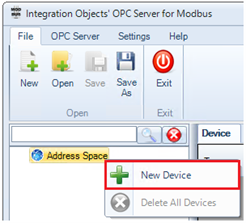
Add New Modbus Device
- Click “Next” then configure the Modbus Device parameters depending on your device type:
- TCP/IP Modbus Device:
- Select “TCP” as Device Type
- Port: The port number used to establish the TCP connection (default for Modbus is typically 502).
- Name: A unique identifier for the device being configured, used to label and organize devices in the OPC server’s address space.
- IP Address: The network address of the Modbus device you want to connect to.
- Slave Identifier: The Modbus slave ID that identifies the specific device on the network to communicate with it.
- Connection Timeout (s): The maximum time (in seconds) the server will wait to establish a connection with the Modbus device before giving up.
- Timeouts Number: The number of consecutive connection timeouts allowed before the connection is considered failed.
- Request Timeout (ms): The maximum time (in milliseconds) the server will wait for a response to a request from the Modbus device.
- Request Timeouts Number: The number of consecutive request timeouts allowed before the server considers the device unresponsive.
- Disable Diagnostics: A setting to disable the check of the device communication status.
- Inter Request Delay (ms): The time (in milliseconds) to wait between sending two read requests to the Modbus device.
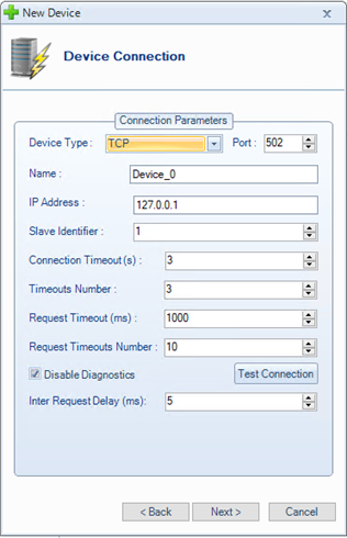
Modbus TCP Device Configuration
- Serial Modbus Device:
- Select “SERIAL” as Device Type
- Port Settings:
- Port ID: The identifier or name of the communication port used to connect to the Modbus device.
- Baud Rate: The baud rate to be used to configure the COM port.
- Data Bit: The number of data bits in each communication frame.
- Parity: The error-checking method for communication.
- Stop Bits: The number of stop bits added to the end of each data packet to indicate the end of transmission.
- Flow Control: The mechanism for controlling the flow of data to prevent buffer overflows.
- Read Timeout (ms): The maximum time (in milliseconds) the OPC Server waits to read data from the device before timing out.
- Write Timeout (ms): The maximum time (in milliseconds) the OPC Server waits to write data to the device before timing out.
- Name: A unique identifier for the device being configured, used to label and organize devices in the OPC server’s address space.
- COM Port: The serial communication port on the computer used to connect to the Modbus device.
- Slave Identifier: The Modbus slave ID that identifies the specific device on the network to communicate with it.
- Connection Timeout (s): The maximum time (in seconds) the server will wait to establish a connection with the Modbus device before giving up.
- Timeouts Number: The number of consecutive connection timeouts allowed before the connection is considered failed.
- Request Timeout (ms): The maximum time (in milliseconds) the server will wait for a response to a request from the Modbus device.
- Request Timeouts Number: The number of consecutive request timeouts allowed before the server considers the device unresponsive.
- Disable Diagnostics: A setting to disable the check of the device communication status.
- Inter Request Delay (ms): The time (in milliseconds) to wait between sending two read requests to the Modbus device.
- Response Delay (ms): The amount of time (in milliseconds) to wait for a response from the target device. This delay may be useful in case of devices with slow performance.
- Transmission Mode: The Modbus communication mode used for data transmission:
- RTU (Remote Terminal Unit).
- ASCII (American Standard Code for Information Interchange).
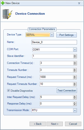
Modbus Serial Device Configuration
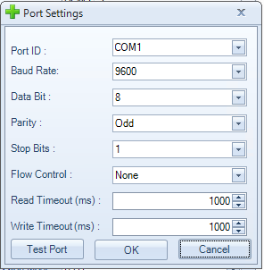
Port Settings
- TCP/IP Modbus Device:
- Click “Test Connection” to test the communication to the Modbus Device using the specified configuration.
- Click “Next” until you complete the device configuration. Then, click “Finish”.
- Right-click on the newly configured device and select “New Tag” from the displayed menu.Adding a New Tag
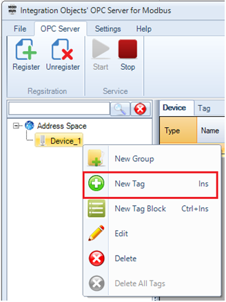
Adding a New Tag
- For each tag to be added:
- Enter a tag name, location type and tag address and datatype.
- Specify the access right that you need to grant to your OPC Tag.
- Click “Add” button then “OK”.
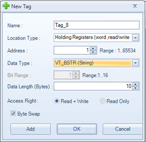
Tag Configuration
Below is a detailed description of the tag parameters:
- Name: The name of the tag that identifies the data point in the Modbus device. This is a unique identifier that can be referenced in the OPC server.
- Location Type: The type of Modbus data that the tag represents. It specifies the location of the data within the Modbus device. There are 4 different types:
- Coils: Represent discrete outputs in Modbus, usually used to control binary devices.
- Discrete Inputs: Represent discrete inputs, typically used for binary devices that provide true/false states.
- Holding Registers: Represent writable analog data. These are 16-bit registers used to read or write data.
- Input Registers: Represent read-only analog data. These are 16-bit registers used to read data.
- Address: The address from where the data will be extracted or modified. The value should be between 1 and 65534.
- Data Type: The type of data, which can be:
- VT_I2: Variable type is 2-byte signed integer.
- VT_I4: Variable type is 4-byte signed integer.
- VT_R4: Variable type is 4-byte real.
- VT_R8: Variable type is 8-byte double.
- VT_UI2: Variable type is an unsigned integer.
- VT_UI4: Variable type is an unsigned long.
- VT_BSTR: Variable type is binary string.
- VT_BOOL: Variable type is Boolean
- Bit Range: This is enabled with Boolean tags whose address type is Holding Register or Input Register. It denotes the range of a bit in one register.
- Data Length (Bytes): Specifies the number of bytes to read or write from the Modbus register.
- Access Right: The data access right, which can be read only or read/write
- Byte Swap: This is used to reverse the order of bytes when necessary, depending on the system’s architecture or how the data is encoded.
- Save your OPC Server for Modbus configuration from the “File” menu then restart the OPC Server for Modbus Service from the “OPC Server” menu.
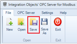
Save Configuration
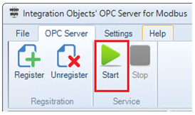
Start the OPC Server for Modbus Service
- Connect to the OPC Server for Modbus using an OPC DA Client and read your Modbus tags, as illustrated below:
You may use our free OPC DA Explorer product available for download from our website.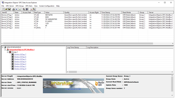
Read Modbus Data from an OPC Client via OPC Server for Modbus
Configure Multiple Tags in the OPC Server for Modbus via CSV File
For bulk configuration, you may proceed as follows:
- After configuring and saving the OPC Server for Modbus configuration (.csv) file from the previous section, open (.csv) files using Excel.
- Add the configuration of other tags by following the format illustrated below. Then save the (.csv) file:
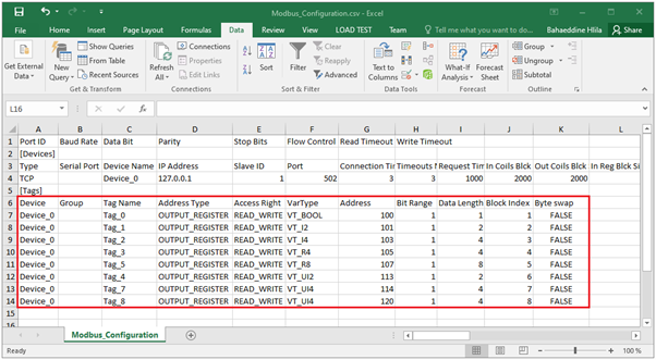
OPC Server for Modbus CSV Configuration
- Open the saved configuration using the OPC Server for Modbus GUI and then click “Save” button as illustrated below:
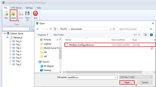
open configuration
- Restart the OPC Server for Modbus service from the “OPC Server” menu for the configuration changes to take effect.

